
Freeze Dryer Diagram: Parts, Flow and Working Principle
Use this labeled freeze dryer diagram to follow water from frozen food to captured ice, identify each major component, and check whether a proposed industrial system is balanced for the real product and batch load.
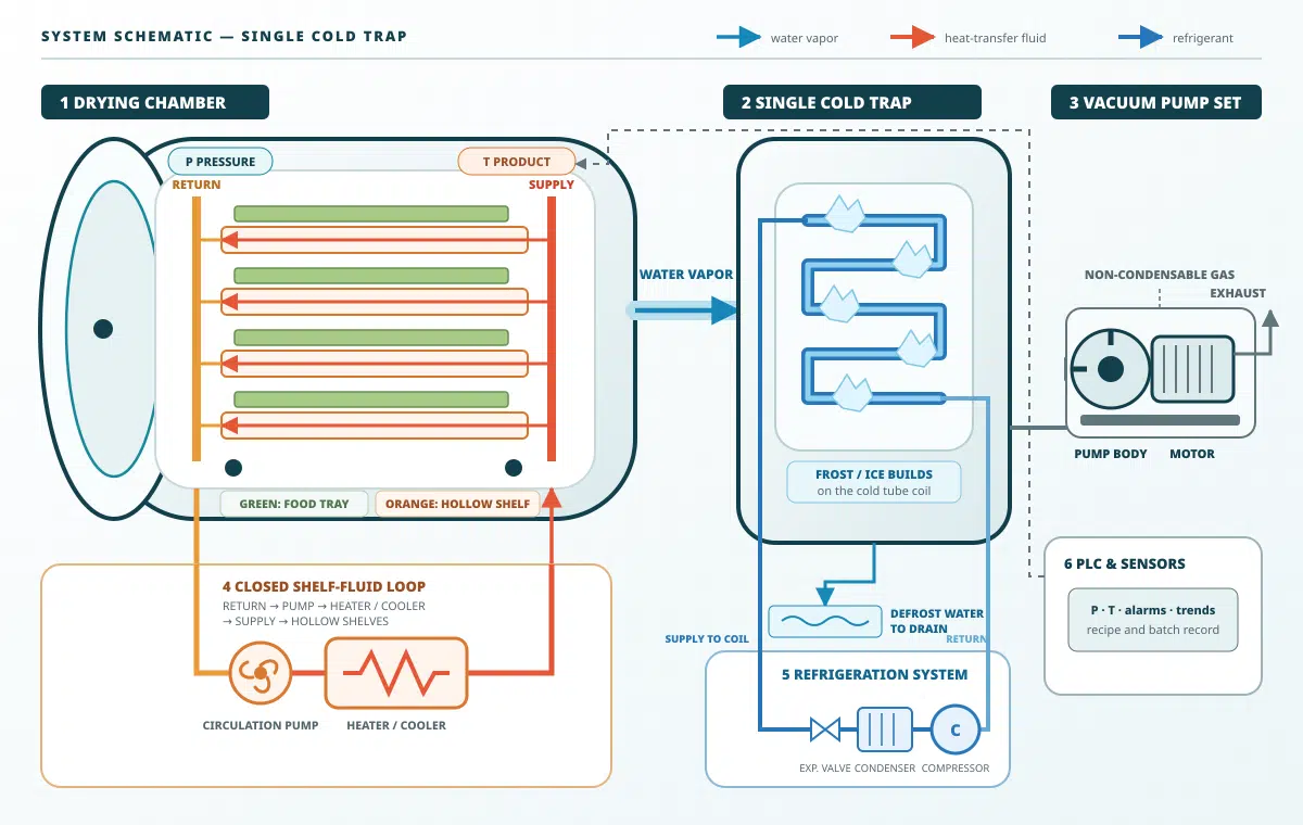
How Does a Freeze Dryer Work?
As shown in the freeze dryer diagram, A freeze dryer freezes the product, lowers chamber pressure, supplies controlled heat so ice sublimates into vapor, and captures that vapor as ice on a colder condenser. Secondary drying then removes part of the remaining sorbed water. This freezing → primary drying → secondary drying sequence is well established, but the safe operating window depends on the food and the equipment.[1]
Industrial performance is therefore a system question. The chamber, tray trolley, heating plates, vapor outlet, condenser, refrigeration system, vacuum pump, sensors and controls must handle the same load at the same time. Food-scale reviews show that geometry, tray contact and radiation can change product temperature during scale-up. Therefore, tray area alone does not prove batch capacity.[2]
Engineering distinction: the condenser captures most of the released water vapor. The vacuum pump establishes low pressure and removes non-condensable gases; it should not be treated as the primary water-capture device.
Complete Industrial Freeze Dryer Diagram
The complete system contains more than a vacuum chamber and pump. In the horizontal design below, a round-door cylindrical chamber and removable tray trolley connect to the condenser. The connection uses a short vapor path. The thermal-fluid circuit, refrigeration system, vacuum system, sensors, PLC and defrost arrangement support the batch. Published food engineering work identifies these same functions and warns that their geometry and heat-transfer behavior change during scale-up.[2] For equipment selection, these subsystems should be evaluated together as part of the complete vacuum freeze dryer system.
The labeled freeze dryer diagram above places each major component in its actual system context. The table below converts the visual layout into practical checks for a food processor or project engineer.
| Component | Main function | What a food processor should check |
|---|---|---|
| Horizontal cylindrical chamber | Holds the tray trolley under controlled vacuum in a round pressure vessel. | Usable tray area, vessel diameter, leak rate, round-door sealing, cleanability, trolley access and vapor-outlet geometry. |
| Tray trolley and heating plates | Support product trays and transfer controlled radiant heat. | Plate uniformity, trolley alignment, tray material, loading density and whether in-chamber shelf cooling is included. |
| Condenser or cold trap | Captures sublimated water vapor as ice. | Usable kg/batch, loaded kg/h capture rate, frost behavior and defrost time. |
| Vacuum system | Creates and controls low chamber pressure. | Loaded pump-down time, valve sizing, leakage, pump configuration and pressure stability. |
| Refrigeration system | Cools the condenser and, where configured, the chamber shelves. | Loaded performance, frost accumulation, ambient design conditions, external versus in-chamber freezing and maintenance access. |
| Sensors and PLC | Measure, control and record the batch. | Sensor type, accuracy, calibration, alarms, recipes and batch-record export. |
The detailed freeze dryer vacuum chamber guide, condenser guide and vacuum pump guide explain those subsystems without forcing this page to duplicate them.
Follow the Water Through the Freeze Dryer
The clearest way to read a freeze dryer schematic is to follow the water. First, heat reaches the frozen product and vapor crosses the growing dry layer. The chamber outlet then carries the vapor, and the condenser deposits it as ice. As the dry layer grows, its resistance can slow mass transfer. Equipment geometry and tray contact can also alter heat input.[1][2]
Water and Gas Paths at a Glance
The icon and text in each card describe the same process step; thin connectors show the direction of movement without dominating the diagram.
Swipe horizontally to follow the complete water-vapor path on mobile.
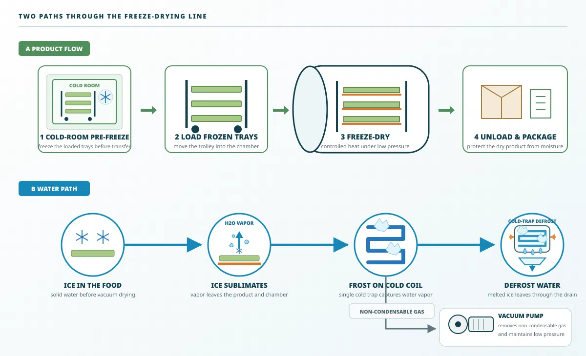
Figure 2. The upper lane follows four product steps: pre-freezing, trolley loading, freeze-drying and packaging. The lower lane follows water from ice in the food to vapor, coil frost and defrost drainage. The gray branch sends non-condensable gas to the vacuum pump.[5]
1. Water Freezes Inside the Food
Freezing creates the ice structure that later becomes a network of pores. Therefore, freezing rate influences both product quality and resistance to vapor flow.
2. Shelves Supply Sublimation Energy
Freeze drying uses controlled heat. However, shelf temperature is not the same as product temperature, so representative product sensors remain necessary.
3. Vapor Moves Through the Dry Layer
As drying continues, the dry layer becomes thicker. Consequently, product thickness, pore structure and chamber geometry can become the limiting resistance.
4. The Condenser Captures the Vapor
The vapor freezes on the colder collecting surface. Frost thickness then increases thermal resistance, so late-batch performance matters more than the no-load minimum temperature.
Freeze Dryer Working Principle in Three Stages
The working cycle has three stages: freezing, primary drying and secondary drying.[1] In the production line shown here, loaded trays are pre-frozen in a cold room and then transferred into the freeze dryer. Some systems support in-chamber shelf cooling, but that is not the configuration illustrated below. A fixed recipe alone does not guarantee repeatability; endpoint behavior can vary with the product, loading and cycle setup.[3]
Cycle Conditions at a Glance
Stage 1 occurs in an external cold room. The frozen load then moves into the freeze dryer for primary and secondary drying.
Swipe horizontally to compare all three cycle stages on mobile.
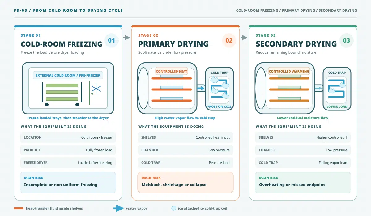
Figure 3. Stage 1 freezes the loaded trays in an external cold room. The frozen load then enters the freeze dryer. Primary drying produces the peak vapor and cold-trap ice load; secondary drying removes the lower residual moisture load.
Freezing
The complete load must reach a stable frozen state before vacuum drying. For the line illustrated here, this occurs in the external cold room before the frozen trays enter the dryer. Freezing history matters because ice-crystal structure becomes the later vapor pathway; the best freezing rate therefore depends on the product rather than a universal recipe.[1]
Primary Drying
Primary drying removes ice by sublimation. The controller balances shelf heat, product temperature, chamber pressure and condenser load. Excess heat can raise product temperature beyond its critical limit and cause melting, shrinkage or structural collapse; insufficient heat lengthens the cycle.[1]
Secondary Drying
After free ice is removed, controlled warming under vacuum reduces remaining sorbed water. The finished batch should meet product-specific acceptance criteria such as residual moisture, center dryness, mass stability, appearance, sensory quality, rehydration performance and consistency across representative tray positions.
Temperature, Pressure and Vapor Flow Must Be Read Together
No single temperature or vacuum number proves that a cycle is correct. Product temperature protects structure, while shelf temperature controls heat input. Chamber pressure affects heat and mass transfer, and condenser performance governs vapor capture. Buyers should ask where every value is measured, under what product load and at which point in the cycle.[1]
- A lower pressure is not automatically faster because extremely deep vacuum can reduce gas-mediated heat transfer.
- A colder no-load condenser does not prove high loaded capture capacity after frost accumulates.
- A powerful pump cannot correct a restricted vapor duct, chamber leak or undersized cold trap.
- A shelf setpoint cannot replace product-temperature measurements at representative locations.
Equipment-capability research also shows that minimum controllable pressure and maximum sublimation rate are dryer-specific and may be limited by vapor-path conductance or condenser overload. That work used pharmaceutical vial systems, so this article applies only the equipment-boundary principle—not its product settings or numerical limits—to food machinery.[5]
The separate guide to freeze drying temperature and pressure covers setpoint development, critical product temperature and endpoint interpretation in greater detail.
How the Freeze Dryer Diagram Changes by Machine Scale
Lab and Pilot Freeze Dryers
Compact pilot systems support product trials, recipe development and scale-up data collection. They should provide adjustable shelf temperature, representative sensors and exportable process records rather than only an automatic consumer cycle.
Commercial Freeze Dryers
Commercial systems use larger horizontal cylindrical chambers, removable tray trolleys, independent refrigeration and vacuum equipment, repeatable recipes, cleaning access and defined utility requirements. Capacity should be expressed as wet loading and water removal, not chamber diameter or volume alone.
Industrial Freeze Dryers
Industrial systems use larger cylindrical pressure vessels, wider chamber outlets, stronger trolley and rail arrangements, planned defrost and service access. Large projects may also use separate or alternating cold traps. Installation space, floor loading, drainage, loading routes and maintenance clearance become part of the process design.
Control and Documentation
As scale increases, batch records, alarms, sensor mapping and utility trends become more important. The freeze dryer monitoring guide explains how data and alarms support repeatability.
Water-Balance Example for Condenser Sizing
A water mass balance should be calculated before tray area is compared. Suppose a batch contains 100 kg of food at 80% moisture and the target final moisture is 3% on a wet basis.
The condenser needs more than 79.38 kg of usable ice capacity after an engineering allowance is added. Total capacity is only one check: the refrigeration system, collecting surface and vapor route must also handle the peak kg/h released during primary drying. Pilot data are needed to estimate that rate; the calculation above is a preliminary mass balance, not a model guarantee.[5]
What Published Food Projects Show
Company-published project records illustrate why a generic freeze dryer working principle must be converted into product-specific loading and cycle data. They are first-party operating records, not independent comparative tests.
| Project | Published operating result | Engineering lesson |
|---|---|---|
| Pear slices, 100 m² system | 1,200 kg per batch, 12-hour drying cycle and 2.21% final moisture. | Loading density and slice preparation must be defined before daily capacity is estimated. |
| Blueberries, 30 m² system | 360 kg per batch, approximately 13-hour cycle and 1.97% final moisture. | Whole fruit structure and skin resistance can change vapor-release behavior. |
| Shrimp, 200 m² system in India | 2,320 kg per batch, approximately 8-hour cycle and 1.68% final moisture. | Seafood loading, pretreatment and product geometry must be validated at representative scale. |
These records are not universal recipes. Plant-food reviews show that cuticle, sugar concentration, composition and sample size can change freeze-drying behavior.[4] Use the projects to define which measurements a supplier should disclose, then validate the buyer’s own product. Additional applications are available in the customer project library.
How Buyers Should Read a Freeze Dryer Drawing
A sales brochure may show only the chamber, tray area and headline temperature. A credible proposal should identify the full vapor path, measurement points, utilities, maintenance clearances and loaded test conditions. Before purchase, request:
- Round chamber, door, trolley rail and loading-clearance drawing
- General arrangement drawing with maintenance and service clearances
- Chamber, tray and effective shelf-area drawing
- Refrigeration and thermal-fluid flow diagram
- Vacuum piping diagram with valve and sensor positions
- Instrument list with measurement range and accuracy
- Electrical load and utility requirement sheet
- Defrost, drainage and cleaning arrangement
- FAT plan covering leak rate, pressure control, temperature mapping and loaded performance
Buyers can use the freeze dryer specifications guide as a checklist when several suppliers present different terminology or test conditions.
Freeze Dryer Diagram Red Flags
A Narrow Cylindrical-Chamber Outlet
A large round chamber can release a high vapor load. If the outlet or connecting duct is too narrow, conductance loss can raise local pressure and slow sublimation even when the vacuum pump is large.
Condenser Capacity Listed Only as kg
Total ice capacity does not show whether the system can capture the peak hourly vapor load.
Vacuum Pump Power Used as the Main Claim
Pump power cannot compensate for leakage, weak refrigeration, heavy frost or poor chamber conductance.
No Representative Product Sensors
Shelf temperature alone cannot confirm the condition of the coldest or thickest product location.
No Defrost and Drainage Route
Ice removal affects turnaround time, hygiene and the number of practical batches per day.
Tray Area Without Loading Data
Area must be combined with kg/m², product depth, water content, cycle time and cleaning time.
These are investigation triggers, not proof that a design will fail. Ask the supplier for test conditions, calculation basis and acceptance criteria before making a comparison.
Information to Send Before Requesting a Freeze Dryer Proposal
A supplier can prepare a more defensible selection when the food and production target are described with measurable inputs. Therefore, the inquiry should include:
- Product name, formula and pretreatment
- Initial moisture and target final moisture
- Slice thickness, particle size or filling depth
- Wet kilograms per batch and target batches per day
- Expected appearance, texture and rehydration
- Available electricity, cooling water and steam conditions
- Factory space, floor location, drainage and access
- Packaging method and shelf-life validation plan
- Required freezing method: external pre-freezer or in-chamber shelf cooling
When product data are incomplete, pilot testing should come before final sizing. The resulting loading density, drying curve, final moisture, center dryness, mass stability, sensory quality, rehydration performance and batch consistency can support a proposal instead of a tray-area estimate. Whole fruit, slices, liquids and high-sugar products should not inherit one another’s cycle assumptions.[4]
Turn Your Product Data Into a Sizing Brief
Send the product, initial moisture, layer thickness, wet load, target daily output and utilities. The engineering team can return a preliminary water balance, identify missing test data, outline condenser and tray-area questions, and shortlist a lab, commercial or industrial range. Final capacity still requires product testing and an agreed acceptance plan.

Technical Reviewer: Zheng Wei
Zheng Wei is the founder of Fuzhou Xing Shun Da Refrigeration Facility Project Co., Ltd. He has participated in food freeze dryer design, refrigeration and vacuum-system planning, equipment production, installation guidance and process testing for the projects published on this website. See the company profile and published project library.
This article combines that first-party equipment experience with scope-limited literature evidence. It does not present one food, pressure, temperature or cycle time as a universal specification.
References and Evidence Scope
The following sources support the process, scale-up, monitoring and equipment-capability statements cited in this article. The pharmaceutical source is used only for the stated equipment-capability principle.
- Nowak D, Jakubczyk E. The Freeze-Drying of Foods—The Characteristic of the Process Course and the Effect of Its Parameters on the Physical Properties of Food Materials. Foods. 2020;9(10):1488. https://doi.org/10.3390/foods9101488
- Ratti C. Freeze drying for food powder production. In: Handbook of Food Powders: Processes and Properties. Woodhead Publishing; 2013:57–84. https://doi.org/10.1533/9780857098672.1.57
- Pisano R, Barresi AA, Fissore D. Innovation in Monitoring Food Freeze Drying. Drying Technology. 2011;29(16):1920–1931. https://doi.org/10.1080/07373937.2011.596299
- Bhatta S, Stevanovic Janezic T, Ratti C. Freeze-Drying of Plant-Based Foods. Foods. 2020;9(1):87. https://doi.org/10.3390/foods9010087
- Tchessalov S, Maglio V, Kazarin P, et al. Practical Advice on Scientific Design of Freeze-Drying Process: 2023 Update. Pharmaceutical Research. 2023;40(10):2433–2455. https://doi.org/10.1007/s11095-023-03607-9 A correction to this article was published in 2024: https://doi.org/10.1007/s11095-024-03768-1.
Authoritative Food-Safety Context
- University of Minnesota Extension: Preserving Food at Home—Freeze-Drying
- UC Agriculture and Natural Resources: Freeze Drying and Microorganism Survival
Food-safety boundary: freeze drying removes moisture but should not be treated as sterilization. Raw-material controls, validated pretreatment, hygiene, packaging and storage requirements still apply.
Frequently Asked Questions
Why is the industrial drying chamber cylindrical?
A cylindrical vacuum vessel distributes external atmospheric pressure efficiently and is suitable for larger repeated-batch systems. The round shape does not determine capacity by itself; usable tray area, trolley layout, vapor-outlet conductance, condenser load and verified cycle time remain essential.
What are the main parts shown in a freeze dryer diagram?
The main parts are the horizontal cylindrical chamber, round door, removable tray trolley or shelf rack, radiant heating plates, wide vapor outlet, condenser or cold trap, vacuum pump, refrigeration system, sensors, valves, PLC controls and defrost drain.
Where does the water go during freeze drying?
Water freezes inside the food, sublimates into vapor under low pressure and then freezes again on the colder condenser surface. After the batch, defrosting turns the collected ice into drainable water.
Does the vacuum pump remove all water vapor?
No. The condenser should capture most of the water vapor as ice. The vacuum pump mainly establishes low pressure and removes non-condensable gases or residual vapor that passes the cold trap.
Why must the condenser be colder than the product?
The colder condenser creates a lower vapor-pressure destination for water vapor. This supports movement from the product toward the cold trap and protects the vacuum pump from the main water load.
Is the lowest possible pressure always best?
No. Very deep vacuum can reduce gas-mediated heat transfer and may not improve sublimation. Pressure, shelf heat, product temperature and condenser performance should be developed together.
How is industrial freeze dryer capacity calculated?
Capacity should begin with wet loading, initial moisture, target final moisture, water removed per batch, peak capture rate, verified cycle time, defrost time and target batches per day. Tray area alone is insufficient.
What drawing should a supplier provide?
A serious proposal should include the general arrangement, round chamber and door dimensions, trolley and rail layout, usable tray area, vapor-outlet size, vacuum and refrigeration flow diagrams, instrument positions, utility loads, defrost and drainage routes, loading clearance and an acceptance-test plan.
Can one freeze dryer process different foods?
Yes, provided the machine offers suitable temperature, pressure, heating and recipe control. However, each food requires its own validated tray loading, freezing method, drying curve and finished-product acceptance criteria.
Conclusion
A useful freeze dryer diagram should represent the actual equipment. In this horizontal cylindrical design, the round chamber, tray trolley, radiant heating plates, wide vapor outlet, condenser, vacuum system and controls work as one vapor-removal system. For a factory project, the next step is to convert that layout into measured loading, water removal, cycle time, freezing method and quality requirements before equipment size is selected.