
Evaluating Freeze Dryer Heat Rejection in Kuwait Food Plants Under Summer Demands
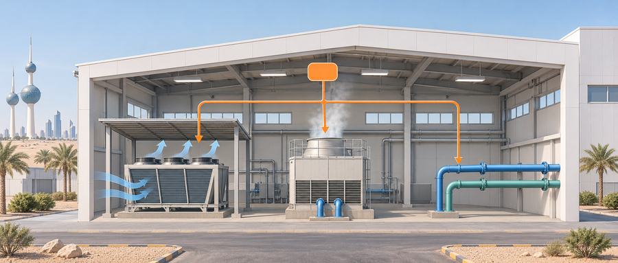
Tracking Sublimation Energy from Product Trays to the Plant Boundary
A factory engineering lead and an enterprise owner walking through a food ingredient facility in Kuwait might inspect an existing utility line while an adjacent processing line sits idle. A pressure gauge on an idle secondary cooling water branch shows steady pressure, and the pipe feels cold to the touch. That quiet reading can easily create false confidence. The immediate equipment decision is whether that branch and the upstream central cooling plant can deliver the required inlet temperature, volumetric flow, and differential pressure while the new freeze dryer and other connected factory lines run simultaneously. Facing an idle pipe, the practical first step is to obtain the manufacturer’s specified coolant inlet temperature, flow rate, differential pressure, and rejected heat duty, and then compare those criteria against concurrent operating measurements or a documented plant cooling load assessment. Without that verification, the factory risks buying an otherwise capable freeze dryer only to find that an undersupplied branch starves the refrigeration condenser during peak summer production.
Understanding why this branch bottleneck occurs begins by distinguishing two mechanical assemblies that share the name condenser. Non-specialist managers are often surprised to hear engineers refer to two separate condensing processes inside the same plant. In a batch food freeze dryer, the ice condenser, also known as the cold trap, sits inside the vacuum vessel or in an adjacent connected vacuum chamber. Its refrigerated surfaces below minus 30 Celsius capture water vapor that sublimates from frozen food pieces and freeze that vapor into solid ice. Outside the vacuum system, the refrigeration condenser transfers thermal energy out of high-pressure refrigerant gas into the factory cooling water loop or outdoor air. The ice condenser collects product moisture under deep vacuum, whereas the refrigeration condenser unloads heat from the thermodynamic cycle into the facility utility network. For detailed internal arrangements, review our guide on freeze dryer condenser configurations.
The heat that the factory cooling system must remove does not come from a mysterious electrical surge. When product ice sublimates under vacuum, it absorbs latent heat from heating shelves. As that vapor desublimates onto the colder ice condenser coils, it releases that latent heat directly onto the refrigeration evaporator. For a simple vapor-compression refrigeration circuit operating near steady state within a defined boundary, the heat rejected at the refrigeration condenser roughly equals the thermal heat absorbed at the cold trap plus the mechanical compressor work transferred into the refrigerant fluid. Some systems route compressor oil cooling or heat recovery exchangers through auxiliary circuits, which diverts a portion of that thermal load away from the main condenser. Plant managers should never calculate cooling duty by adding up the electric heating shelf nameplate rating, the total machine electrical connected load, or thermal heat quantities already accounted for on the evaporator side. Furthermore, commercial machines do not all share a single refrigeration circuit, and peak vapor generation does not always occur during one fixed drying phase across every recipe.
A common engineering mistake is confusing a batch’s cumulative starting water inventory with the water actually captured as ice and the instantaneous thermal power rate. For instance, in a hypothetical calculation using three hundred kilograms of initial water or a twenty-hour cycle, that starting mass is not the amount of ice captured on the cold trap or a drying rate. Sizing requires distinguishing cumulative ice captured per batch in kilograms, the fluctuating vapor release rate in kilograms per hour, and the instantaneous heat rejection rate in thermal kilowatts. In a published refrigeration system design analysis for vacuum freeze drying, Xu Yansheng [1] provided calculation examples for apple slices and beef slices that demonstrated how sublimation rates, drying durations, and peak-to-average vapor ratios differ across foods. Sizing cannot rely on historical multipliers from those calculation examples. To evaluate supplier quotes fairly, the factory must require the supplier to state the peak heat-rejection rate delivered to the named plant utility interface in thermal kilowatts, the duration and timing of that peak, all coincident refrigeration loads, and the exact evaporating and condensing temperatures alongside entering air or water conditions.
Selecting Heat Rejection Architectures for Kuwait Summer Conditions
Deciding how to reject condenser heat in Kuwait requires balancing local weather extremes against plant infrastructure. Records published by the Kuwait Meteorological Center [2] document severe summer conditions that alternate between extremely hot, dusty desert periods and intense humid spells driven by Persian Gulf marine winds. These official climate records provide necessary regional context rather than a single manufacturer design-day standard. Because local weather swings between dry heat and humid air, factory leads must understand how atmospheric variables govern different heat rejection equipment.
Air-cooled condensers discharge heat directly into outdoor air, which means their rejection capacity depends on the dry-bulb temperature of the air entering the installed finned coil. In Kuwait summer weather, direct solar radiation, recirculated warm discharge air between building walls or parapets, and limited physical clearance around the unit can elevate the coil inlet dry-bulb temperature well above ambient meteorological readings. Fin fouling from airborne desert dust degrades coil heat transfer and can restrict airflow, while limited coil clearance can also restrict airflow or contribute to recirculation depending on layout. In contrast, evaporative cooling towers rely on water evaporation, which makes entering-air wet-bulb temperature the governing physical limit. The water temperature leaving an evaporative cooling tower equals the entering wet-bulb temperature plus the tower design approach at the specified thermal load and water flow. The term approach denotes the temperature difference between the leaving water stream and the entering wet-bulb air. A dry closed-loop cooler and an evaporative cooling tower reject heat through different physical mechanisms, because a dry cooler cannot bring water below ambient dry-bulb temperature. Facilities teams must evaluate dry hot afternoons and humid Gulf evenings as separate design cases using verified site measurements. When a plant installs an intermediate plate heat exchanger to protect clean refrigeration condensers from gritty cooling tower water, engineers must account for temperature approach and hydraulic pressure drops on both fluid sides of that heat exchanger.
| Rejection Architecture | Equipment and Site Boundary | Critical Engineering Verifications |
|---|---|---|
| Packaged Air-Cooled Condenser | Refrigeration package with integral or roof-mounted finned coils, condenser fans, and refrigerant piping connected to the freeze dryer skid. | Measure design dry-bulb temperature at the installed coil intake, verify physical clearance against hot air recirculation, assess fin dust resistance, and check fan motor electrical loads. |
| Dedicated Evaporative Cooling Tower | Water-cooled shell-and-tube or plate condenser connected to a dedicated outdoor evaporative tower, circulating pumps, and water treatment loop. | Verify peak local wet-bulb temperature, tower approach at rated heat load, makeup water availability, blowdown purge rates, chemical water treatment, and pump head capacity. |
| Shared Factory Cooling Water Circuit | Refrigeration condenser tied into an existing central chilled water or cooling tower supply and return header inside the processing plant. | Confirm maximum supply water temperature during peak summer production, guaranteed branch flow and differential pressure at the tie-in point, and central utility headroom. |
Comparing these options fairly requires evaluating identical product batch sizes, finished food quality standards, and summer site conditions. When considering evaporative cooling, factory managers must recognize that cooling tower circulation flow and makeup water consumption represent different engineering quantities. Circulation flow in cubic meters per hour describes the continuous water stream moving through the condenser tubes to absorb heat. In contrast, makeup water replaces water lost during operation. Guidelines from the United States Department of Energy [3] clarify that makeup volume for a properly maintained cooling tower equals the sum of evaporation, blowdown, and drift when leaks and tank overflow are eliminated. Evaporative loss removes heat through phase change, blowdown drains a fraction of mineral-concentrated water to prevent scale deposits on heat exchange surfaces, and drift represents tiny droplets carried out in the exhaust air stream. Furthermore, cooling water for condenser heat exchange must never be confused with auxiliary cooling water for vacuum pumps, or utility water consumed during chamber sanitation and hot water defrosting. Each water demand follows distinct quality requirements and operating schedules. Upstream pumps, tower fans, and central chillers also impose electrical loads across the facility boundary that must be included when evaluating operational demands. For broader facility integration details, see our overview of commercial freeze dryer setup requirements.
Validating Condenser Performance Under Full Sublimation Load
The final operational risk in factory cooling integration is signing off on equipment after an unloaded commissioning run. Running a freeze dryer empty confirms only the specific functions and test conditions exercised, such as generic pump operation, basic control response, and circulation, but an empty chamber generates zero sublimation vapor. Although other refrigeration loads may still operate during such checks, an empty chamber provides no product sublimation latent heat to the cold trap. Consequently, empty commissioning cannot establish whether cooling water flow or heat rejection capacity will hold up under a representative loaded batch and peak summer concurrent utility loads.
This operational distinction between empty checks and loaded verification is well established in process engineering. In a published case analysis of freeze dryer refrigeration system problems, Guo Xing [4] examined an existing two-circuit pharmaceutical unit where a low-pressure return shut-off valve on one circuit had been replaced, after which empty tests reached their operating targets. However, subsequent loaded testing during sublimation revealed poor refrigeration and weaker vapor capture in that specific circuit. Investigation identified a refrigeration-circuit restriction, and a loaded retest following repair confirmed that the affected circuit cooled properly and kept pace with the companion circuit under that test. While that case involved pharmaceutical machinery and did not stem from cooling water faults, its practical lesson directly applies to food factories: empty runs cannot reveal capacity bottlenecks that emerge only when refrigeration circuits carry genuine sublimation loads.
A rigorous acceptance trial requires prior written agreement on the representative food product, batch loading and tray geometry, drying recipe, and target moisture and texture criteria. The parties must also agree on concurrent factory users and their operating states, summer entering-air dry-bulb temperature for air units or wet-bulb temperature for evaporative towers, and machine water supply conditions where relevant. During this trial, the engineering team must record time-aligned trend logs capturing signals the parties specify at the installed equipment, including measured entering and leaving water temperatures, continuous flow rate and differential pressure across the condenser, outdoor coolant conditions, refrigeration suction and discharge pressures, compressor motor electrical current, chamber vacuum, ice condenser surface temperatures, and product core temperature profiles, carefully distinguishing chamber and cold trap signals from outdoor coolant measurements.
Testing documentation must state explicitly what each proof covers. If initial testing took place during mild weather, summer rejection capability must be recorded as conditional until an agreed hot-condition retest or a substantiated engineering assessment using relevant supplier selection and performance data covers the agreed summer conditions and is accepted as evidence. Once simultaneous measurements or substantiated assessments confirm that the branch delivers the required inlet temperature, flow, and differential pressure while maintaining safe condensing pressures under full sublimation load with concurrent factory operations, the plant can clear the utility connection decision. However, this engineering utility sign-off verifies mechanical heat removal under peak load and must never be conflated with statutory food safety compliance or product release authorization.
Reviewing Factory Heat Rejection Parameters for Batch Equipment
Food ingredient manufacturers planning to add industrial batch freeze drying capacity can review their facility cooling limits before finalizing equipment configurations. Our company manufactures commercial food batch freeze dryers designed for robust industrial food processing. Plant engineering teams are welcome to share their planned food product types, wet batch loading weights, cycle requirements, and site utility water data for an initial technical scoping discussion. To review equipment specifications and thermal interface requirements for your facility, contact our engineering team.
References
- Xu Yansheng. 食品真空冷冻干燥设备制冷系统的设计 (Refrigeration system design for food vacuum freeze-drying equipment). 制冷, 1997 (4), pp. 43–46.
- Kuwait Meteorological Center. Climate of Kuwait.
- U.S. Department of Energy, Federal Energy Management Program. Best Management Practice #10: Cooling Tower Management.
- Guo Xing. 冻干机制冷系统的典型问题及案例分析 (Typical problems and a case analysis of freeze-dryer refrigeration systems). 机电信息, 2014 (11), pp. 31–33. DOI 10.19514/j.cnki.cn32-1628/tm.2014.11.007.
About the Author: Zheng Wei
Founder & Freeze-Drying System Engineer
Fuzhou Xing Shun Da Refrigeration Facility Project Co., Ltd.
Zheng Wei participates in food freeze-drying trials, equipment selection, vacuum-system configuration, refrigeration planning, installation guidance, process optimization, and project handover. The project experience covers fruit, vegetables, cooked foods, seafood, meat, dairy products, herbs, and extracts.