
Freeze Dryer Norge: Coordinating Complete Systems and Split Industrial Supply
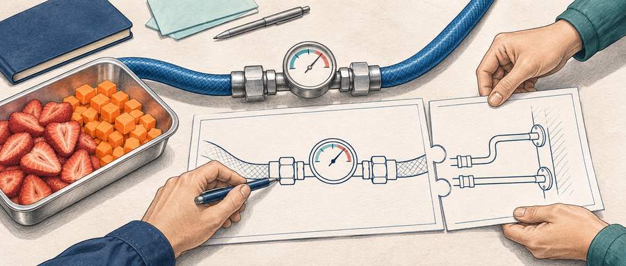
Illustrative planning relationship showing food-batch specifications and utility interface points coordinated between an industrial drying chamber and plant services.
In this article
- Evaluating Food Freeze-Drying Equipment for Plant Expansions
- The Interdependent Physics of Industrial Food Freeze Drying
- Multi-Supplier Precedents in Norwegian Food Production
- Comparing Complete Turnkey Packages Against Split Local Scope
- Managing Physical, Utility, and Control Interfaces
- Joint Food-Load Handover: Proving the Assembled Installation
- Lifecycle Support, As-Built Documentation, and Spares
- Structuring Your Project Requirements
Evaluating Food Freeze-Drying Equipment for Plant Expansions
Consider a food processor expanding production who compares an integrated system offer against a split scope combining drying machinery with local refrigeration or installation contractors. Because actual site connections depend on the agreed equipment configuration, the project team must determine which party establishes the operating conditions and control responses at each interface, and how the assembled plant will be proven on the intended food product.
Both procurement paths can be considered for an industrial food facility. Comparing them requires looking beyond upfront machinery pricing to evaluate how heating, vacuum, and refrigeration must function together under load, who assumes responsibility for conditions at each connection boundary, and what technical proof confirms the completed plant will perform as required.
The Interdependent Physics of Industrial Food Freeze Drying
Freeze drying preserves food by converting solid ice directly into water vapor through sublimation, bypassing the liquid phase. As analyzed by Luo and Shu (2017), this transformation involves coupled heat and mass transfer. Controlled thermal energy must reach the frozen sublimation front within the product. The liberated water vapor then moves through the developing porous dry structure of the food into the chamber, where refrigerated cold-trap surfaces capture it as ice to maintain the low operating pressure required for sublimation.
This physical chain creates an interdependent dynamic between three sub-systems:
- Controlled Heat Delivery: Supplies thermal energy to the food trays by an engineered heating method suited to the machine design, balanced against sublimation rates so product temperature remains within safe limits for the food structure.
- Vapor Transport and Capture: Water vapor flows through the chamber toward the refrigerated cold trap, where cold condensing surfaces collect it by desublimation back into ice.
- Vacuum Regulation: Mechanical vacuum pumps evacuate air and non-condensable gases to establish and hold chamber operating pressure within the target range.
If vapor-capture capacity is insufficient for the released sublimation rate—such as when condensing surfaces warm under peak vapor load—chamber pressure can rise. Depending on the product’s actual temperature and structure, this pressure increase may slow sublimation, alter heat transfer, or risk softening and structural damage to the drying food. Because heat delivery, vapor transport, and refrigeration capture operate as one thermodynamic system, separate machinery elements must function in strict coordination.
Multi-Supplier Precedents in Norwegian Food Production
Industrial food batch freeze dryers form a dedicated machinery category distinct from laboratory or pharmaceutical units, configured to match specific food products, material handling flows, and facility services. Commercial batch platforms, such as GEA RAY batch systems, illustrate this industrial category where equipment is engineered around defined production duties.
In Tromsø, food producer Drytech produces field rations and food products and is expanding production. According to PTG (2026), PTG Kuldeteknisk together with Maritim Sveiseservice supply new drying chambers for the project, drawing on longstanding regional engineering cooperation in demanding industrial refrigeration, surface design, cleaning, and maintenance.
However, public reports of industrial cooperation describe the project arrangement rather than disclosing proprietary commercial contracts, control architectures, or loaded factory acceptance test data. For a food factory planning an expansion, the specific division of engineering duties cannot be inferred from general industry examples and must be explicitly established for the project.
Comparing Complete Turnkey Packages Against Split Local Scope
When comparing quotes between a single machine supplier and a split scope involving local contractors, neither procurement label automatically defines the engineering scope or guarantees complete integration. The key task is to verify what physical equipment is delivered, where connection boundaries lie, what utility conditions are required at each interface, and which party coordinates overall commissioning.
| Evaluation Factor | Integrated Complete System | Split Supply (Machinery + Local Services) |
|---|---|---|
| Interface Definition | Review quotation for internal piping, component matching, and explicit terminal connections to external plant utilities. | Physical tie-in points, flow rates, temperatures, and pressures must be explicitly defined and coordinated across separate supply contracts. |
| Controls and Communication | Review quotation for control scope, programmed protective responses, and external hardware or signal interfaces. | Signal exchanges, run/alarm status, and emergency response logic must be agreed, programmed, and verified between separate control panels. |
| Refrigeration Integration | Confirm which vapor-capture condensers and refrigeration components are included, along with matched cooling duties. | Allows alignment with local refrigeration contractors or existing plant infrastructure, requiring rigorous capacity and temperature matching. |
| Commissioning and Deviations | Confirm whether quotation designates a commissioning coordinator, defined test boundaries, and operational performance criteria. | A designated project coordinator or engineering lead must oversee joint commissioning and resolve operational deviations across supplier interfaces. |
Both sourcing models can succeed, but they distribute engineering and project coordination differently. A complete equipment package consolidates component matching within the vendor’s scope, though plant utility connections must still be managed. A split scope allows greater flexibility to utilize local engineering capabilities, requiring active coordination of interfaces, boundaries, and combined testing. For technical background on facility layout and utility preparation, consult our guide to commercial freeze dryer setup.
Managing Physical, Utility, and Control Interfaces
Establishing clear interface conditions before comparing supply offers allows the project team to evaluate how each proposal supports the planned food production duty. Clarifying these tie-in boundaries early helps identify operational interactions across plant utilities, as illustrated by the following shared service situation.
1. Shared Utilities and Operational Variations
Consider a hypothetical scenario where an industrial freeze dryer connects to a central plant cooling-water loop that also serves other facility loads. When measured at idle or during low plant activity, the cooling loop may show acceptable inlet temperature and static pressure. However, if adjacent equipment starts up during normal production, shared pumping demand and heat loads may alter the available flow rate or supply temperature.
Depending on the refrigeration system design, a rise in cooling-water temperature can elevate condensing head pressure, reducing net refrigeration capacity at the cold trap. To prevent unexpected bottlenecks, project specifications should define the exact physical tie-in point, the required flow rate, pressure, and temperature envelope under agreed combined operating conditions, and assign responsibility for measuring conditions and resolving any shortfall.
2. Control Interlocks and Fault Logic
When refrigeration, vacuum, or heating sub-systems operate with separate control enclosures, the signal and safety interfaces must be carefully structured. Depending on the equipment architecture, an exchange of simple status contacts or a dedicated communication link may be selected to coordinate operation.
- Signal Definitions: Explicitly define which operational signals—such as running status, cold-trap temperature permissives, ready-to-dry flags, and fault alarms—must be exchanged between control units.
- Engineered Protective Response: Agree on the exact programmed safety responses for out-of-range events, such as defining how heating should be regulated or halted if refrigeration performance drops, based on the specific machine configuration and food stability requirements.
- Programming and Verification Scope: Specify which engineering team is responsible for coding, testing, and signing off on the interface communication routines before commissioning under load.
3. Nordic Ambient Conditions and Plant Services
Site ambient conditions, seasonal variations, and facility standby states must be factored into the specific heat-rejection design rather than relying on general assumptions about regional climate. While cool outdoor air can aid heat dissipation, outdoor coolers require freeze-protection engineering for sub-zero winter temperatures. Furthermore, secondary services such as heating media, defrost water loops, steam supplies, or compressed air are strictly configuration-dependent and must be confirmed directly against the manufacturer’s engineering documentation.
Joint Food-Load Handover: Proving the Assembled Installation
Commissioning checks performed in an empty chamber provide essential baseline verification of mechanical integrity and vacuum tightness, but they do not reproduce the sublimation vapor load released by an active food batch. The physical sublimation mechanisms analyzed by Luo and Shu (2017) show that heating, vapor transport, and cold-trap ice capture operate interdependently during drying. Based on these principles, our engineering recommendation is to demonstrate the complete assembled installation under a representative food sublimation load to verify integrated operational performance.
To ensure clear operational accountability across all contributing parties, project agreements should establish an agreed protocol for demonstrating the completed installation. This involves distinguishing the specific purposes of initial checks from the final loaded demonstration:
- Component and Mechanical Verification: Checking component physical mounting, electrical wiring, pressure containment, sensor calibrations, and utility supply tolerances using appropriate pre-start inspection procedures.
- No-Load Dry Run: Operating the empty equipment through defined cycles to verify vacuum pump-down curves, heating and cooling response rates, and basic control sequencing.
- Representative Food-Load Demonstration: Processing an agreed test batch of representative food material under target operating conditions to verify integrated system performance under real sublimation demand.
For the food-load demonstration, define clear test parameters beforehand:
- Food Matrix and Preparation: Define the representative food product, slice or piece geometry, pre-freezing method, and loading distribution across the trays.
- Wet Batch Mass: Specify the total prepared wet mass and loading density per square meter of tray area.
- Cycle Boundaries and Quality Criteria: Agree on the exact start and end events for the measured cycle along with target duration and objective food quality endpoints, using agreed, valid measurement and sampling procedures.
- Utility Conditions and Deviation Handling: Record utility operating parameters during the trial run and designate a named coordinator responsible for investigating and resolving any process deviations.
During loaded operation, frost accumulation on the cold-trap condensing surfaces is the intended mechanism for vapor capture. The critical performance criterion is that the cold trap maintains sufficient surface area and temperature to condense the sublimation vapor load without exceeding the allowable operating chamber pressure. For detailed protocols on documentation, cycle monitoring, and validation methodologies, refer to our technical overview of food freeze dryer validation.
Lifecycle Support, As-Built Documentation, and Spares
The commercial success of a food manufacturing investment extends years past the commissioning date. When operating industrial equipment in Norway, long-term operational uptime depends on the quality of documentation and service handovers negotiated before contract signing.
Project handovers should include accurate as-built electrical schematics, piping and instrumentation diagrams (P&IDs), and refrigeration drawings that incorporate all site modifications, including interface terminal assignments. The operations team requires clear maintenance instructions and component identification for serviceable items—such as vacuum pump fluids, door gaskets, valve seals, and refrigeration filter cores—along with defined physical clearance and service access envelopes for the chosen plant layout.
Designating qualified technical support contacts, agreed diagnostic access procedures, and clear escalation paths across system boundaries provides practical preparation that helps technical teams trace and resolve operational issues across the installation.
Structuring Your Project Requirements
Choosing between an integrated turnkey package and a split scope with local engineering partners is a project management decision based on facility priorities and technical capacity. Neither approach eliminates the need to manage physical boundaries, utility conditions, and commissioning oversight. If your facility has experienced project engineering personnel and strong relationships with regional contractors, a split scope can effectively utilize local resources. If minimizing internal engineering coordination is preferred, an integrated scope consolidates equipment boundaries under a single supplier contract.
To explore machine sizing, chamber layout, and refrigeration matching for your facility’s planned expansion, review standard industrial batch freeze dryer configurations.
When your project team is preparing to evaluate proposals, our team can assist with a preliminary technical configuration discussion. Providing details regarding your specific food material, prepared wet batch weight, production schedule, existing facility utilities, and planned local contractor scope allows for a preliminary discussion of drying area, cold-trap capacity, and interface requirements.
References
- Luo N, Shu H. Analysis of Energy Saving during Food Freeze Drying. Procedia Engineering. 2017;205:3763–3768. DOI: 10.1016/j.proeng.2017.10.330.
- GEA. RAY® Freeze Dryer — batch freeze-drying systems for food production.
- PTG. Defense Contract Creates Local Ripple Effects: Calls Politicians to Look to Tromsø. 16 February 2026.
About the Author: Zheng Wei
Founder & Freeze-Drying System Engineer
Fuzhou Xing Shun Da Refrigeration Facility Project Co., Ltd.
Zheng Wei participates in food freeze-drying trials, equipment selection, vacuum-system configuration, refrigeration planning, installation guidance, process optimization, and project handover. The project experience covers fruit, vegetables, cooked foods, seafood, meat, dairy products, herbs, and extracts.